Introduction to Automotive Ethernet
IEEE 1000BASE-T
Completion requirements
Physical connection
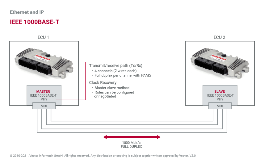
For the physical connection, the IEEE 1000BASE-T requires four channels, each of which has two twisted wires. The wire pairs are used to transmit symmetrical differential voltages that represent previously encoded symbols.
Encoding and decoding
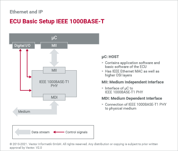
A sender encodes the symbols corresponding to the desired bit stream. A receiver decodes the symbol stream, thereby recovering the sent bits. In contrast to IEEE 100BASE-T1 and IEEE 100BASE-TX, IEEE 1000BASE-T uses a combination of 8B1Q4, Trellis, Viterbi, and PAM5 methods for coding and decoding as well as for generating the differential voltages. These methods are implemented in the IEEE 1000BASE-T PHY, which is integrated as a dedicated block in the ECU. The PHY establishes the connection between the physical medium and Ethernet controller.
Cables and connectors
Standardized Cat5e cables are typically used for IEEE 1000BASE-T. All eight available wires are needed for connecting the four channels. The assignment of the wire pairs is specified in the two standards EIA/TIA-568A and EIA/TIA-568B. These standards also contain the pin assignment for the normally used RJ45 plug connectors and sockets.
Topology
Only two nodes are ever connected to one cable. Thus, only point-to-point connection topology is available. More than two nodes can be connected using a coupling element. A switch is normally used here, which as a Layer 2 coupling element allows connection to multiple physical connections and can independently forward messages from branch to branch.
Full duplex
Due to the PAM5 procedure, two interconnected nodes can send and receive simultaneously on four channels (full duplex). As a sender, a node adds its own differential voltage to the wires; while as a receiver, it subtracts its own voltage from the applied total voltage. The result of the subtraction corresponds to the voltages that were sent by the opposite node. This mechanism is a component of the echo cancellation method that is used in other Ethernet systems.
Synchronization
In order for differential voltages to be added or subtracted, the two nodes must know when a new symbol begins. This means that both nodes must be synchronized to the symbol stream. This is done with the help of a master node and slave node. The master generates a continuous symbol stream to which the slave is synchronized. In contrast to IEEE 100BASE-T1, the roles are not fixed but rather are negotiated using an auto negotiation mechanism.
Last modified: Monday, 23 January 2023, 1:04 PM