Introduction to Automotive Ethernet
DoIP
Completion requirements
Background
Ethernet has already been used for a few years for diagnostics and here, in particular, for flashing ECUs. This application area is already very attractive for vehicle manufacturers and suppliers for the simple reason that it enables flash cycles to be significantly reduced in production and car repair shops, for example.
ISO 13400
Diagnostics over IP is now readily available and is specified in ISO 13400. It makes no difference which physical layer is used as long as it supports the transmission of IP packets. For example, besides Ethernet, the use of WLAN and UMTS as physical media is also conceivable with DoIP.

Transport protocol
The important thing here is that DoIP does not represent a diagnostic protocol according to ISO 13400 but rather an expanded transport protocol. This means that the transmission of diagnostic packets is defined in DoIP, but the contained diagnostic services continue to be specified and described by diagnostic protocols such as KWP2000 and UDS.
Requirements
A requirement for DoIP is the support of UDP and TCP. UDP is used for transmission of status or configuration information. A TCP connection, on the other hand, enables transmission of actual diagnostic packets via a fixed communication channel. This ensures high reliability of data transmission and enables automatic segmentation of large data packets. TCP and UDP must be implemented in the diagnostic tester as well as in each ECU with DoIP diagnostic capability (DoIP Node) and in each diagnostic gateway (DoIP Gateway or DoIP Edge Node).
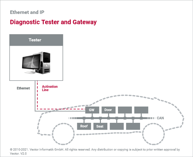
Diagnostics tester
Same as for diagnostics with classic bus systems, a diagnostic tester enables the sending of diagnostic requests. Testers can take the form of external devices, such as in repair shops, or on-board testers in the vehicle. The receiving ECU must, in turn, process the diagnostic requests and return an associated diagnostic response to the tester. However, this requires that DoIP as well as underlying layers be implemented in each directly diagnosable ECU.
Diagnostics gateway
So that a separate implementation is not needed for each ECU, DoIP allows the use of diagnostic gateways. Thus, all ECUs of a vehicle that are connected via a classic bus system or network can be made available in principle. The gateway assumes the role of the intermediary. Requests of the tester are forwarded to internal networks so that a desired ECU can receive and process them. As soon as a response from the requested ECU is available, the gateway routes this back to the tester.
Logical addresses
A diagnostic gateway always requires two pieces of information in order to forward diagnostic requests and responses. First, it needs a logical address that uniquely identifies the ECU to be diagnosed in the vehicle. Second, the gateway must know which messages on the respective bus system or network will be used to send diagnostic requests and to receive diagnostic responses. Both pieces of information must be available for an ECU for it to be accessible via the gateway.
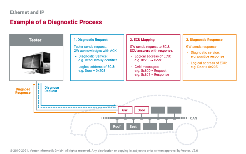
Diagnostics process
During diagnosis, the diagnostic gateway first receives the request from the tester. The request contains the diagnostic packet with the desired diagnostic service and the logical address of the ECU to be diagnosed. The gateway then removes the diagnostic packet and packs it into a message that can be sent on the utilized bus system or network. For example, if an ECU is to be addressed using CAN, the gateway sends out a message with the associated identifier (e.g., 0x600) to this bus. It then waits for a response from the ECU. As soon as the response is received from the associated bus system or network (e.g., CAN with identifier 0x700), the gateway returns the response for the original diagnostic service to the tester. For this, it adds the logical address of the ECU so that the tester can uniquely assign the response. This allows a tester to send requests for multiple ECUs to different bus systems and networks without waiting for a sequential response.
Last modified: Thursday, 7 October 2021, 4:58 PM