FlexRay Bus
FlexRay technology is designed for data rates up to 10 Mbit/s. This and the omission of cost-intensive shielded lines represent great challenges in assuring electromagnetic compatibility. Therefore, the FlexRay physical layer defines certain mechanisms for increasing immunity against high-frequency interference fields and electrostatic discharge (ESD) and for reducing noise emissions.
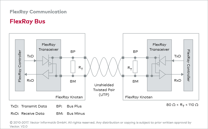
Physical signal transmission in the FlexRay cluster is based on the transmission of differential voltages. This approach renders interference voltages induced by motors, ignition units and switch contacts harmless. Emissions are limited by the relatively low differential voltages (2 Volt for the bus level “Data_1”, -2 Volt for the bus level “Data_0”).
Because of its differential signal transmission, the FlexRay bus consists of two lines: Bus Plus (BP) and Bus Minus (BM). Twisting of the two lines reduces the magnetic field considerably, so twisted line pairs are typically used in practice — for cost reasons usually without shielding.
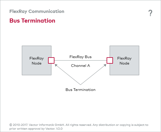
Because of finite signal propagation speed, the effects of transient responses (reflections) increase with higher data rates and growing bus length. Termination of the ends of the communication channel by termination resistors prevents reflections in a FlexRay cluster.
Because the FlexRay specification specifies a load between 40 and 55 Ω, values of the bus termination resistors must lie between 80 and 110 Ω. Therefore, a cable whose impedance lies between 80 and 110 Ω should be used for transmission.
Instead of providing each of the ends of the communication channel with an individual bus termination resistor, the ends of the FlexRay bus may be terminated by a split bus termination. The split bus termination acts like a low-pass filter; high-frequency signals are shunted to ground without affecting DC voltage relationships.


