FlexRay Bus Interface
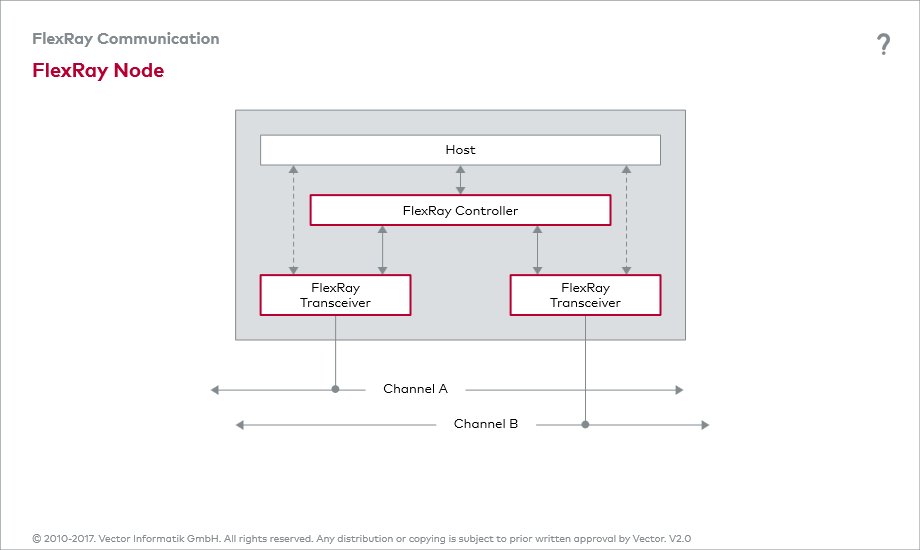
It is not possible to connect a FlexRay controller directly to the physical transmission medium. While the FlexRay controller works with binary signals, the physical transmission medium uses differential signal transmission. What is needed is a physical bus interface. This role is covered for the most part by the FlexRay transceiver.
The FlexRay transceiver converts the logical signal stream received from the FlexRay controller into a differential signal stream. In the other direction, it converts the physical differential signal stream received from the FlexRay bus into a logical signal stream.
Besides serving as the interface to the FlexRay controller, the FlexRay transceiver also has an interface to the host, which primarily relates to the two control lines STBN (Standby) and EN (Enable Input). The host uses these two control lines to control the FlexRay transceiver, which can essentially enter four different states: Normal, Standby, Sleep or ReceiveOnly. The last two states are optional.
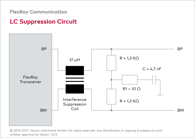
A key characteristic of a FlexRay transceiver is its especially high level of electromagnetic compatibility. Nonetheless, interference suppression coils are used to further reduce emissions: this prevents disturbances to other electronic systems to a large extend.
The use of LC suppression circuits
in the FlexRay transceivers, with relatively high suppression coil
impedance values, suppresses any interference currents that might be
generated by asymmetrical circuits. In addition, the low pass filter,
consisting of the coupling capacitor of the split termination and an
interference suppression coil, shunts high-frequency interference to
ground.
Although coils with higher inductance provide better
results due to their greater noise suppression, the effects of leakage
inductance on signal integrity must be considered. The Electrical
Physical Layer Specification prescribes the following values for
interference suppression coils: Line resistance < 2 Ω; inductance
>50 μH and leakage inductance <1 μH.
A slight disadvantage of the LC circuit is that the combination of leakage inductance and coupling capacitor form an oscillating circuit, which in conjunction with the switching processes of the FlexRay transceiver lead to overshoots of the bus signals.


