- Overview
- 1. Introduction
- 2. General Description of the Protocol
- 3. Document Structure
-
4. Fundamentals
- 4.1. Names and Addresses
- Device Names
- Device Address
- 4.2. Parameter Group
- General
- Example of a Global Parameter Group
- Example of a Specific Parameter Group
- Parameter Groups reserved specially for the Protocol
- 4.3. Data Management
- Suspect Parameter Number (SPN)
- SLOT Definition
-
5. Network Management
- Network Access
- 5.1. Address Conflict
- Solution and Configurations
- Handling in a Dynamic Network
- 6. Transport Protocols (Multi-packet Messages)
- 7. Diagnostics
Introduction to J1939
Structure and Type of a Parameter Group
Completion requirements
Structure
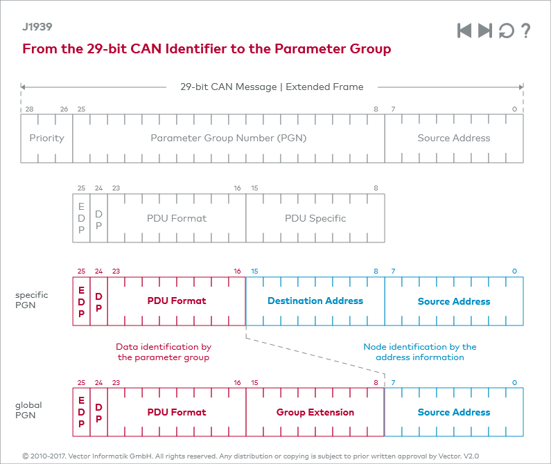
The J1939-21 document defines the scheme according to which the 29-bit CAN identifier must be interpreted. Similarly as for the 8-byte data field of a CAN message in which different signals are defined by a start bit and length, the CAN identifier is subdivided into different segments for a parameter group. By this only a part of the identifier represents the PGN itself, the rest is interpreted as source address, destination address, priority, and data page. The graphic “From the 29-bit CAN Identifier to the Parameter Group” presents the structure of a J1939 CAN identifier.
PGN Format
The graphic shows that the PDU Specific segment has more than one interpretation. The content of this segment is used for one thing to extend the PDU Format segment and define a PGN and for another thing to specify a destination address. The rules for this are as follows:
- If the value in the PDU Format segment is < 240, the content of PDU Specific is interpreted as the destination address. One speaks here of a PGN in PDU Format 1 or of a specific PGN. A PGN in PDU Format 1 can be sent explicitly to a destination address using point-to-point communication, but the global address (255) can also be used. In this way a specific PGN can also be transmitted globally, i.e., to all network nodes.
- If the PDU Format segment has a value >= 240, the PDU Specific segment is interpreted as a group extension. This means that there is no destination address and the message will always be transmitted to all network nodes. PDU Format and PDU Specific represent a 16-bit value that corresponds to the PGN. In this case, the PGN has PDU Format 2 and is called global PGN.
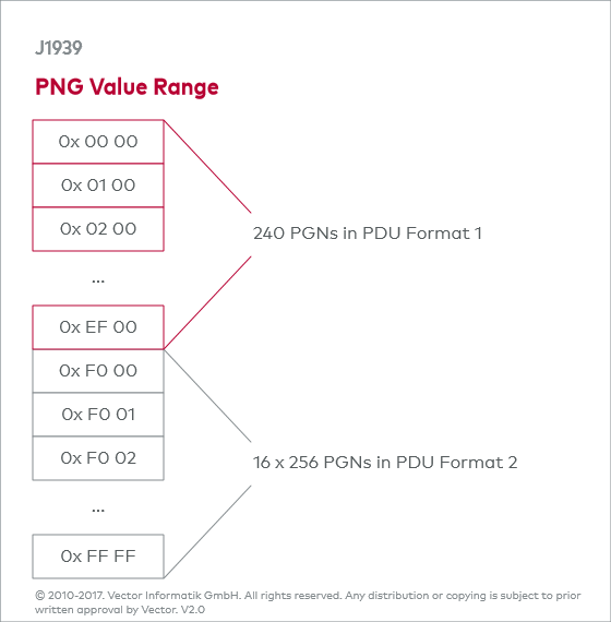
Then how are specific PGNs represented if no address information is needed, for example in the specification? The following applies here: The PGN is extended with ‘00’ instead of the address information. This means:
If the PDU format segment contains 0xEE, the PGN is 0xEE00.
This yields the numeric range for the PGNs shown in graphic “PGN Value Range”.
PGN Sections
The two bits “Data Page” and “Extended Data Page” are also part of the PGN and are included for counting as the two most significant bits. As a result, the numeric range is arranged in four PGN pages, but only 3 are used for J1939.
This yields (240 + (16 * 256)) * 3 = 13,008 possible PGNs.
The following data page definitions are available:
| Extended Data Page Bit | Data Page Bit | Description |
|---|---|---|
| 0 | 0 | SAE J1939 Page 0 PGNs |
| 0 | 1 | SAE J1939 Page 1 PGNs (preferred by the NMEA 2000®) |
| 1 | 0 | SAE J1939 – reserved – |
| 1 | 1 | Defined by ISO 15765-3 (Important: No J1939 layout!) |
Last modified: Thursday, 12 April 2018, 9:24 AM