Signal Transmission
Single Wire
No differential voltage signals can be used for physical signal transmission. Instead, a conventional single-wire line (single wire) is used with defined voltage levels for logic one and logic zero. The typical topology is a line bus.
Voltage and Logical Levels
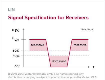
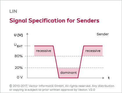
To assure sufficient noise immunity, the supply voltage of the ECU electronics and the vehicle ground (see figure: Drivers) are used as the reference potential for the bus level. A level of less than 40% of the supply voltage is interpreted as a logic zero by the receiver. The receiver interprets as logic one all levels that lie above 60% of the supply voltage (see figure: Signal Specification for Receivers). Senders transmit a voltage level below 20% for logic zero and a voltage level above 80% for logic one (see figure: Signal Specification for Senders).
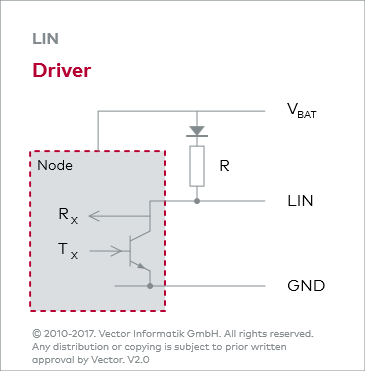
Open Collector Circuit
In terms of circuitry, a cluster corresponds to an open collector circuit. All nodes are passively connected to the bus via transceivers. A pull-up resistor ensures that the bus level nearly matches the supply voltage (high level) when the Tx transistors of all nodes are in the off state. As soon as a Tx transistor conducts in the on state, the bus level is pulled nearly to ground (low level). The low state therefore represents a dominant level that overwrites the recessive high state.
Pull-Up- and Master-Resistor
The pull-up resistor value is 30 kΩ at the slave and 1 kΩ at the master. In contrast to the slave, the pull-up resistor at the master must be externally implemented. A diode in the collector branch prevents power supply of the node over the bus if there is no supply voltage.