Network Management
State Machine
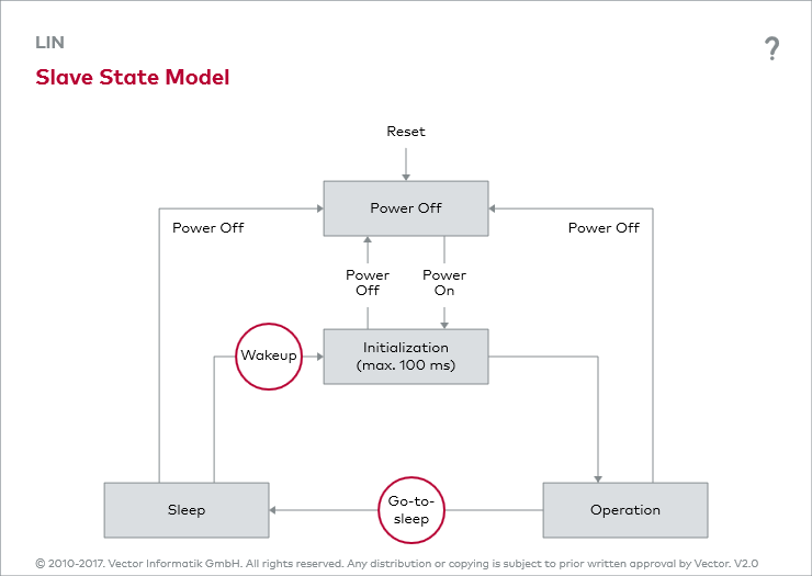
A separate network management is defined in the protocol. It provides for four states of the slaves: Power Off, Initialization, Operation and Sleep. State transitions are also defined (see interactive figure: Slave State Model). Power On switches a slave to the Initialization state. This must be accomplished within 100 ms. Then the slave independently switches to the operating state.
Sleep Command
The master can put all slaves in the Sleep state by transmitting the Go-to-sleep command. This command is a Master Request Frame, whose first data byte has the value 0x00 (corresponds to NAD=0). The seven additional data bytes are transmitted as 0xFF.
Stand-alone Sleep
The slaves also transition to the Sleep state if there is no bus activity for four to ten seconds. According to specification, it is not absolutely necessary for the transition to this state to go hand in hand with the transition to the Low Power state. This means that the microcontroller is not absolutely switched to an energy savings mode in which unnecessary hardware resources are shut off.
Wakeup
Besides the master, each slave also has the ability to wake up the cluster. To do this, it places a wakeup signal on the bus (see interactive figure: Slave State Model). This signal is a dominant pulse that lasts a minimum of 250 µs and a maximum of 5 ms. After detecting a wakeup, the nodes leave the Sleep state and transition to the Initialization state. After another 100 ms they switch to the Operating state.
"Sleepy" Master
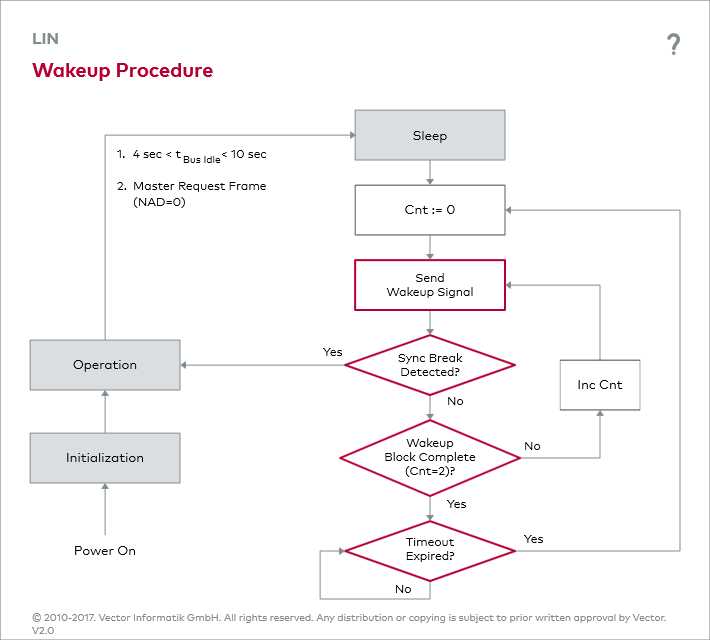
If a slave is responsible for the wakeup and it does not detect any header for another 150 ms after initialization, then the node sends another wakeup signal (see interactive figure: Wakeup Procedure). If this and the next wakeup attempts fail (3 wakeup signals = 1 wakeup block), the slave stops the wakeup procedure for 1.5 seconds, and it may then begin again if applicable. In the end, this depends on the system design requirements.


