- Overview
- 1. Introduction
- 2. CAN Communication
- 3. CAN Framing
- 4. CAN Bus Access
- 5. CAN Data Protection
-
6. CAN FD
- Motivation
- Advantages and Consequences
- New Types of Frames
- Details of a CAN FD Frame
- Distinguishing CAN from CAN FD Frames
- Compatibility of CAN and CAN FD Controllers
- Accelerated Transmission
- Indicating too many Errors
- Length of the Data Field
- More Data with the same Security
- Changed Rules for Bit Stuffing and CRC Calculation
CAN Network
Structure
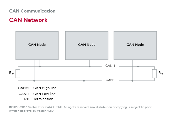
A CAN network consists of a number of CAN nodes which are linked via a physical transmission medium (CAN bus) In practice, the CAN network is usually based on a line topology with a linear bus to which a number of electronic control units are each connected via a CAN interface. The passive star topology may be used as an alternative.
Physical layer
An unshielded twisted two-wire line is the physical transmission medium used most frequently in applications (Unshielded Twisted Pair — UTP), over which symmetrical signal transmission occurs. Typically, UTPs have wire cross-sections between 0.34 mm2 and 0,6 mm2. Line resistance should be less than 60 mΩ.
Boundary conditions
The maximum data rate is 1 Mbit/s. A maximum network extension of about 40 meters is allowed. At the ends of the CAN network, bus termination resistors contribute to preventing transient phenomena (reflections). ISO 11898 specifies the maximum number of CAN nodes as 32.

