- Overview
- 1. Introduction
- 2. CAN Communication
- 3. CAN Framing
- 4. CAN Bus Access
- 5. CAN Data Protection
-
6. CAN FD
- Motivation
- Advantages and Consequences
- New Types of Frames
- Details of a CAN FD Frame
- Distinguishing CAN from CAN FD Frames
- Compatibility of CAN and CAN FD Controllers
- Accelerated Transmission
- Indicating too many Errors
- Length of the Data Field
- More Data with the same Security
- Changed Rules for Bit Stuffing and CRC Calculation
Twisted Pair
Symmetrical signal transmission
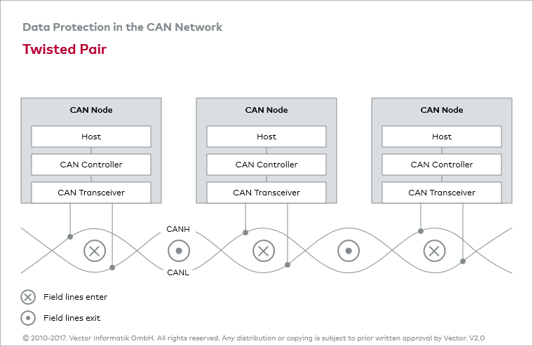
Interference voltages, which can be induced by motors, ignition units and switch contacts, for example, can effectively be rendered harmless by symmetrical signal transmission. In symmetrical signal transmission, external noise acts equally on both lines.
Difference formation
Difference formation can be used to eliminate noises – the useful signal remains unaffected. Symmetrical signal transmission results in a physical transmission medium (CAN bus) consisting of two lines: the CAN-High line (CANH) and CAN-Low line (CANL).
Magnetic fields
With regard to symmetrical signal transmission we exploit the fact that the magnetic fields around the wires superpose. The electric fields within the wires and as a result the magnetic fields around them are exactly opposite to one another. If the wires are run closely adjacent to one another the magnetic fields superpose to almost zero. This is used to cancel electromagnetic emission. Close adjacency is guaranteed by twisting the pair of CAN wires. We speak of twisted pairs.
More enlacement =
less inductive effects
By twisting the wires, the conductive loop is shifted into the individual conductors. Ideally, the magnetic fields will exhibit opposite directions in each sub-segment, which leads to the mutual cancellation of any induced voltages or inductive effects. The effectiveness of twisting increases with the number of wraps. At least 30 wraps per meter yields good results.

