- Overview
- 1. Introduction
- 2. CAN Communication
- 3. CAN Framing
- 4. CAN Bus Access
- 5. CAN Data Protection
-
6. CAN FD
- Motivation
- Advantages and Consequences
- New Types of Frames
- Details of a CAN FD Frame
- Distinguishing CAN from CAN FD Frames
- Compatibility of CAN and CAN FD Controllers
- Accelerated Transmission
- Indicating too many Errors
- Length of the Data Field
- More Data with the same Security
- Changed Rules for Bit Stuffing and CRC Calculation
Termination
Characteristic impedance
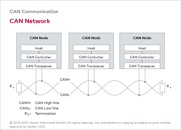
With increasing data rates, transient phenomena in the form of reflections can be expected on the CAN bus due to finite signal propagation. This is why the bus ends in High-Speed CAN networks must be terminated with the characteristic impedance of the physical transmission medium. The characteristic impedance of the communication channel is 120 Ohm.
Termination resistor
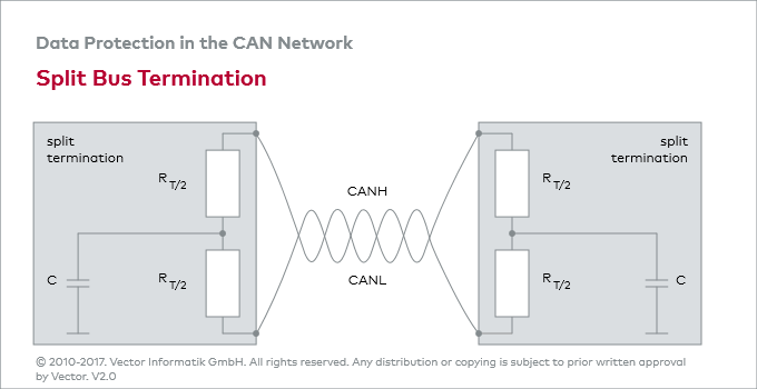
Instead of providing a single bus termination resistor at each of the ends of the communication channel, the ends of the CAN bus may be terminated with a split bus termination instead.
A split bus termination, consisting of two identical resistors (60 Ohm) and one capacitor (typically 4.7 nF), acts like a low-pass filter; high-frequency signals are shunted to ground without affecting the d.c. voltage relationships. Measurements have shown that this can improve noise immunity and reduce emissions.


