- Overview
- 1. Introduction
- 2. CAN Communication
- 3. CAN Framing
- 4. CAN Bus Access
- 5. CAN Data Protection
-
6. CAN FD
- Motivation
- Advantages and Consequences
- New Types of Frames
- Details of a CAN FD Frame
- Distinguishing CAN from CAN FD Frames
- Compatibility of CAN and CAN FD Controllers
- Accelerated Transmission
- Indicating too many Errors
- Length of the Data Field
- More Data with the same Security
- Changed Rules for Bit Stuffing and CRC Calculation
CAN Bus
Differential signals
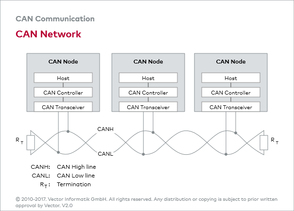
Physical signal transmission in a CAN network is based on transmission of differential voltages (differential signal transmission). This effectively eliminates the negative effects of interference voltages induced by motors, ignition systems and switch contacts. Consequently, the transmission medium (CAN bus) consists of two lines: CAN high line (CANH) and CAN low line (CANL).
Twisted pair
Twisting of the two lines reduces the magnetic field considerably. Therefore, in practice twisted pair conductors are generally used as the physical transmission medium.
Bus termination
Due to finite signal propagation speed, the effects of transient phenomena (reflections) grow with increasing data rate and bus extension. Terminating the ends of the communication channel using termination resistors (simulation of the electrical properties of the transmission medium) prevents reflections in a high-speed CAN network.
The key parameter for the bus termination resistor is the so-called characteristic impedance of the electrical line. This is 120 Ohm. In contrast to ISO 11898-2, ISO 11898-3 (low-speed CAN) does not specify any bus termination resistors due to the low maximum data rate of 125 kbit/s.

