- Overview
- 1. Introduction
- 2. CAN Communication
- 3. CAN Framing
- 4. CAN Bus Access
- 5. CAN Data Protection
-
6. CAN FD
- Advantages and Consequences
- New Types of Frames
- Details of a CAN FD Frame
- Distinguishing CAN from CAN FD Frames
- Compatibility of CAN and CAN FD Controllers
- Accelerated Transmission
- Indicating too many Errors
- Length of the Data Field
- More Data with the same Security
- Changed Rules for Bit Stuffing and CRC Calculation
Motivation
Highly increasing number of signals
In the decades since the introduction of the CAN bus the fabric of embedded systems in vehicles has changed profoundly. Arguably the most evident change is quantity: Had there been some hundreds of signals to be communicated at the time CAN was introduced, today the numbers are within the five digit range.
New requirements,
new bus systems
Consequently the rise in data traffic led to ever higher bus loads on the CAN buses. Aside from the rising demand in bandwidth, an increasing need for deterministic system behavior encouraged the development of new bus systems. So for infotainment purposes the MOST bus was created with band widths of up to 150 Mbit/s. The deterministic FlexRay bus offers bandwidths of 10Mbit/s suitable for driver assistance functionality. On the low end of the bandwidth spectrum LIN was introduced as a low cost solution for tasks in the sensor-actor-area. These new tailor-made bus systems cover niches. Notwithstanding CAN has remained to be the predominant bus system in vehicles.
CAN is not replaced
Only rarely CAN needs to be replaced with buses capable of higher transmission rates, such as FlexRay. Mainly higher costs for the hardware as well as an immense development effort to switch systems to new technologies speak to the contrary.
CAN's lack of bandwidth often is circumvented by applying a higher number of CAN buses. But this involves using gateways to transfer data between these buses.
CAN performance limit
The limiting factor for the bandwidth of CAN is due to one of its core properties: During specific phases of a message transmission multiple network nodes may be in transmission mode at the same time. This may be the case at the beginning of a transmission during the arbitration phase and is always true in the acknowledge field at the end of a message. This means the transmission time of one bit must not be shorter than it takes its voltage level to propagate from a node on one end of the bus to one on the other — and back again. For example: On a CAN bus of 40 meters in length the maximum transmission rate is about 1 Mbit/s in order to fulfill the required transmission time of one bit.
Less bit time is enough
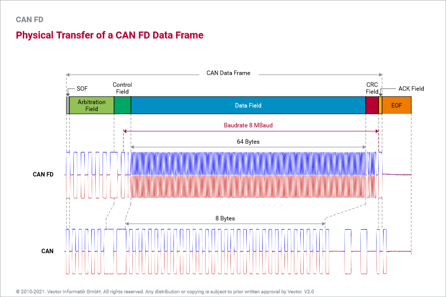
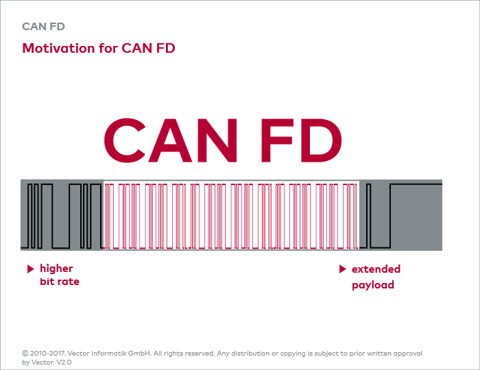
However during the part between the arbitration phase and the acknowledgement field of a CAN frame only one transmitter is allowed. Hence in this part of the frame there is no restriction on the minimum duration of a bit time. And what would be — so engineers at Bosch thought — if we increased the transmission rate during this portion of a CAN frame? You only would need to toggle between two different transmission rates: A slow one at the beginning and end of a CAN frame and a fast one in the middle. Exactly this is the fundamental idea of CAN FD.


