- Overview
- 1. Introduction
- 2. CAN Communication
- 3. CAN Framing
- 4. CAN Bus Access
- 5. CAN Data Protection
-
6. CAN FD
- Motivation
- Advantages and Consequences
- New Types of Frames
- Details of a CAN FD Frame
- Distinguishing CAN from CAN FD Frames
- Compatibility of CAN and CAN FD Controllers
- Accelerated Transmission
- Indicating too many Errors
- Length of the Data Field
- More Data with the same Security
- Changed Rules for Bit Stuffing and CRC Calculation
CAN Node
Electronification
Along with increasing electronification of automobiles, the quantity and complexity of the software is growing rapidly as well. Some luxury vehicles already have over 1000 software functions. In many bus systems, over 70 electronic control units (ECUs) are at work. An ECU that performs its tasks in a CAN network is referred to as a CAN node.
Increasing complexity
In the beginnings of ECU networking, an adequate implementation of the CAN interface involved a simple CAN driver — which provided an essentially simple hardware-independent interface for the application — together with a CAN controller and a CAN transceiver. Today, it is no longer possible to do without an operating system, network management functions or diagnostics. The software complexity, which has meanwhile become enormous, makes it necessary to standardize the ECU infrastructure.
Software harmonization
Uniform software reduces development effort and simplifies maintenance. It also contributes toward increased reuse and interchangeability of software components between different vehicle platforms as well as between OEMs (Original Equipment Manufacturers) and suppliers.
AUTOSAR
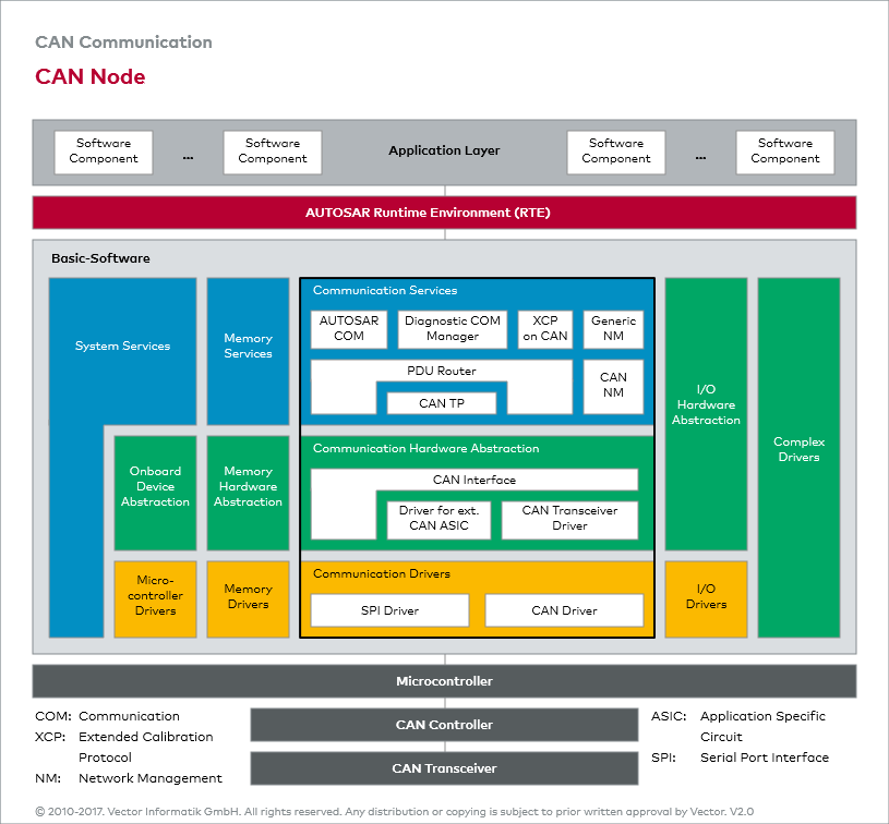
AUTOSAR (AUTomotive Open System ARchiteture) provides a reference architecture for the ECU software. The centerpiece of this reference architecture is the AUTOSAR Runtime Environment (RTE), which completely decouples the network from the software components of the application. The runtime environment provides uniform services to the software components in the form of basic software. From bottom to top, it is made up of three levels: Microcontroller Abstraction Layer, ECU Abstraction Layer, Service Layer.
CAN node structure
The figure “CAN Node” depicts the structure of a modern CAN node. Of great interest is the “Communication Services” area. AUTOSAR COM (Communication) provides standard communication services, diagnostic services (Diagnostic COM Manager) and network management services (Generic NM/CAN NM). The PDU Router (PDU: Protocol Data Unit) handles internal node communication between the individual communication layers and coordinates communication between AUTOSAR COM, the Diagnostic COM Manager and CAN TP (Transport Protocol).

