- Overview
- 1. Introduction
- 2. CAN Communication
- 3. CAN Framing
- 4. CAN Bus Access
- 5. CAN Data Protection
-
6. CAN FD
- Motivation
- Advantages and Consequences
- New Types of Frames
- Details of a CAN FD Frame
- Distinguishing CAN from CAN FD Frames
- Compatibility of CAN and CAN FD Controllers
- Accelerated Transmission
- Indicating too many Errors
- Length of the Data Field
- More Data with the same Security
- Changed Rules for Bit Stuffing and CRC Calculation
CAN Bus Levels
Bus connection
Physical signal transmission in a CAN network is based on differential signal transmission. The specific differential voltages depend on the bus interface that is used. A distinction is made here between the high-speed CAN bus interface (ISO 11898-2) and the low-speed bus interface (ISO 11898-3).
Voltage levels
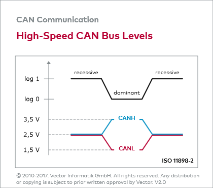
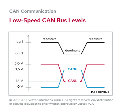
ISO 11898-2 assigns logical “1” to a typical differential voltage of 0 Volt. The logical “0” is assigned with a typical differential voltage of 2 Volt. High-speed CAN transceivers interpret a differential voltage of more than 0.9 Volt as a dominant level within the common mode operating range, typically between 12 Volt and -12 Volt.
Below 0.5 Volt, however, the differential voltage is interpreted as a recessive level. A hysteresis circuit increases immunity to interference voltages. ISO 11898-3 assigns a typical differential voltage of 5 Volt to logical “1”, and a typical differential voltage of 2 Volt corresponds to logical “0”.
The figure “High-Speed CAN Bus Levels” and the figure “Low-Speed CAN Bus Levels” depict the different voltage relationships on the CAN bus.


