- Overview
- 1. Introduction
- 2. CAN Communication
- 3. CAN Framing
- 4. CAN Bus Access
- 5. CAN Data Protection
-
6. CAN FD
- Motivation
- Advantages and Consequences
- New Types of Frames
- Details of a CAN FD Frame
- Distinguishing CAN from CAN FD Frames
- Compatibility of CAN and CAN FD Controllers
- Indicating too many Errors
- Length of the Data Field
- More Data with the same Security
- Changed Rules for Bit Stuffing and CRC Calculation
Accelerated Transmission
Bit Rate Switch
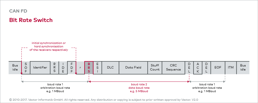
After a reserve bit r for future extensions to CAN FD a bit called Bit Rate Switch (BRS) follows. When dominant, baud rate 2 is equal to baud rate 1, so no accelerated transmission will occur.
If BRS is recessive, the part of the CAN FD frame marked red in the graphic, will be transmitted at the higher baud rate 2. For all CAN FD controllers on one bus both transmission rates have to be configured uniformly.
Baudrate of 5MBit/s
In the graphic baud rate 2 is defined as 5 MBaud which corresponds to 5 Mbit/s, as the bits and their physical representations, i.e. the voltage levels, are of the same duration. This value is not made up from thin air, since laboratory experiments have proven that most of the transceivers used for traditional CAN, will also be able to cope with 5 Mbit/s. Of course higher transmission rates are also possible with adequate transceivers. One will have to wait and see which transmission rates are possible in an electromagnetically much more violent environment as found in real vehicles.
Higher data rate between BRS and CRC Delimiter
The shift from baud rate 1 to baud rate 2 occurs at the sampling point of the BRS, the shift from baud rate 2 back to baud rate 1 at the sampling point of the CRC delimiter directly before the acknowledgement bit.
In order for the receivers to be perfectly synchronized with the sender despite the high transmission rate, directly prior to it a second hard synchronization is performed.

