- Overview
- 1. Introduction
- 2. CAN Communication
- 3. CAN Framing
- 4. CAN Bus Access
- 5. CAN Data Protection
-
6. CAN FD
- Motivation
- Advantages and Consequences
- New Types of Frames
- Details of a CAN FD Frame
- Distinguishing CAN from CAN FD Frames
- Compatibility of CAN and CAN FD Controllers
- Accelerated Transmission
- Indicating too many Errors
- Length of the Data Field
- More Data with the same Security
- Changed Rules for Bit Stuffing and CRC Calculation
Communication Principle
Decentralization
Safety-critical applications, such as those in the powertrain area, place severe demands on a communication system’s availability. So it would be disadvantageous to assign responsibility for bus distribution to just a single bus node. Failure of this vulnerable bus node would cause all communication to fail. A much more elegant solution is to decentralize bus access, so that each bus node has the right to access the bus.
Event driven
That is why a CAN network is based on a combination of multi-master architecture and line topology: essentially each CAN node is authorized to place CAN messages on the bus in a CAN network. The transmission of CAN messages does not follow any predetermined time sequence, rather it is event-driven.
The communication channel is only busy if new information actually needs to be transmitted, and this allows for very quick bus accesses. In principle, real-time data transmissions on the magnitude of milliseconds are no problem in a CAN network, because of the ability to quickly react to asynchronous events and very high data rates up to 1 MBit/s.
Receiver-selective addressing
A method of receiver-selective addressing is used in a CAN network to prevent dependencies between bus nodes and thereby increase configuration flexibility: Every CAN message is available for every CAN node to receive (broadcasting). A prerequisite is that it must be possible to recognize each CAN message by a message identifier (ID) and node-specific filtering. Although this increases overhead, it allows integration of additional CAN nodes without requiring modification of the CAN network.
Communication on CAN
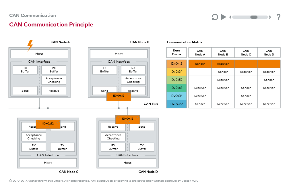
The animation “CAN Communication Principle” gives you the opportunity to practice with message transmission in a CAN network. You can also learn how to use a CAN communication matrix and acceptance filtering. Read through the instructions so that you can fully utilize the entire functionality of the animation.
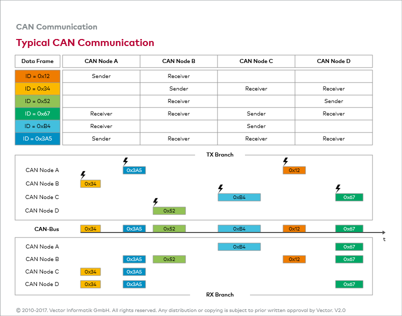
The figure “Typical CAN Communication” directly follows the animation “CAN Communication Principle” and shows you a typical communication sequence. It shows the communication matrix underlying a CAN network, as well as the resulting send and RX branches.


