- Overview
- 1. Introduction
- 2. CAN Communication
- 3. CAN Framing
- 4. CAN Bus Access
- 5. CAN Data Protection
-
6. CAN FD
- Motivation
- Advantages and Consequences
- New Types of Frames
- Details of a CAN FD Frame
- Distinguishing CAN from CAN FD Frames
- Compatibility of CAN and CAN FD Controllers
- Accelerated Transmission
- Indicating too many Errors
- Length of the Data Field
- More Data with the same Security
- Changed Rules for Bit Stuffing and CRC Calculation
CRC and Acknowledgement
Transmission reliability
One of the greatest challenges of serial communication in the automotive environment is to guarantee an extremely high level of reliability in transmission. The CRC method that is used (CRC: Cyclic Redundancy Check) represents one of the most powerful error detection methods.
CRC sequence
In the CRC method, a CRC sequence is computed based on the bits to be transmitted (from SOF up to and including the data field) and a generator polynomial G(x) defined by ISO 11898-1. The CRC sequence is appended to the bits to be transmitted. The overall polynomial is a multiple of the bits to be transmitted. The receiver of the overall polynomial can then detect — with very high reliability — whether a transmission error occurred (exception: CRC sequence itself was corrupted by a disturbance), i.e. if division by the generator polynomial yields a remainder.
Acknowledgement
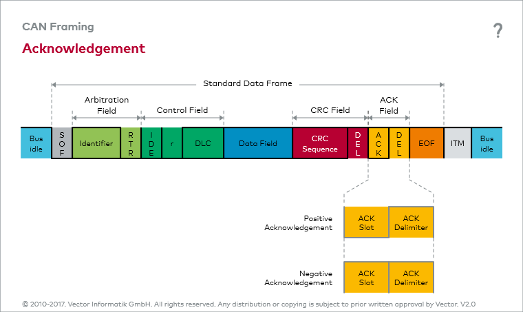
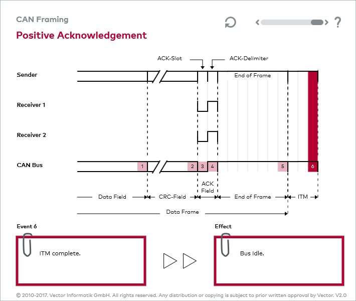
Based on the result of this division, each receiver steers the acknowledgement, independent of any acceptance filtering. A receiver acknowledges either positively or negatively. A dominant level in the ACK slot represents a positive acknowledgement, while a recessive level represents a negative acknowledgement.
ACK delimiter
The ACK delimiter is always transmitted recessively for the purpose of error tracking. Since the sender transmits both the ACK slot and the ACK delimiter recessively, one positive acknowledgement is sufficient to confirm the correctness of the message transmission to the sender. That is why the acknowledgement method in the CAN network is referred to as a node-neutral positive acknowledgement.
An interactive animation on acknowledgement invites you to interactively study acknowledgement in the CAN network. The figure assumes a CAN network with one sender and two positively acknowledging receivers.
ACK error and
error flag
In node-neutral positive acknowledgement, negatively acknowledging CAN nodes are overwritten and at first remain unheard. To assure network-wide data consistency, they send an error flag after the ACK delimiter.
If there is not even one positive acknowledgement, the recessive ACK slot is not overwritten by any receiver, the sender detects an ACK error and terminates the ongoing message transmission by sending an error flag. An ACK error indicates an error caused by the sender or that there are no receivers on the bus.


