- Overview
- 1. Introduction
- 2. CAN Communication
- 3. CAN Framing
- 4. CAN Bus Access
- 5. CAN Data Protection
-
6. CAN FD
- Motivation
- Advantages and Consequences
- New Types of Frames
- Details of a CAN FD Frame
- Distinguishing CAN from CAN FD Frames
- Compatibility of CAN and CAN FD Controllers
- Accelerated Transmission
- Indicating too many Errors
- Length of the Data Field
- More Data with the same Security
- Changed Rules for Bit Stuffing and CRC Calculation
Bit Stuffing
Synchronization
A basic prerequisite for correct data transmission is synchronized communication partners. The dominant-to-recessive signal edge of the start bit serves to produce synchronism (Start Of Frame — SOF) of a CAN message. Afterwards, a resynchronization mechanism is used to maintain synchronism up to the end of the message transmission.
Resynchronization
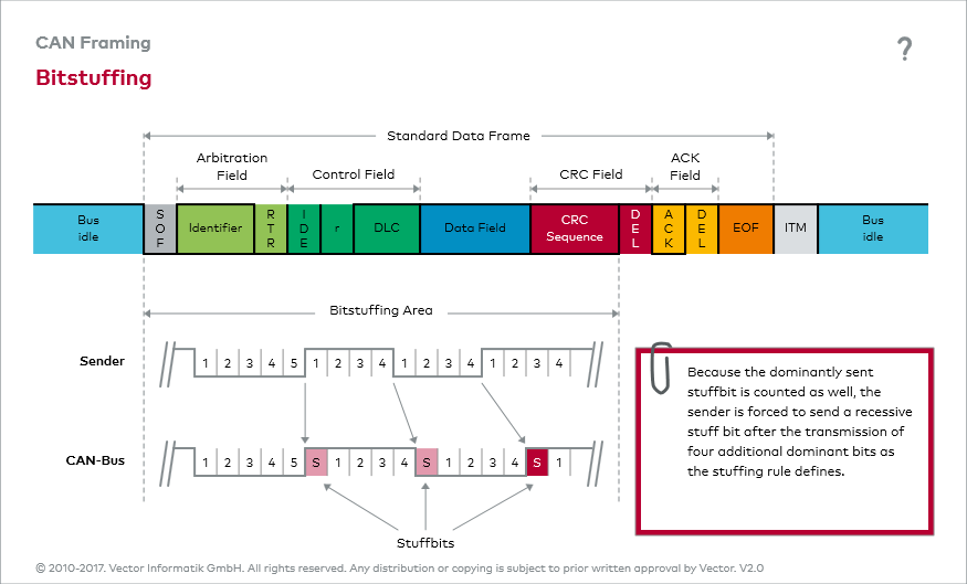
The resynchronization mechanism is based on evaluation of recessive-to-dominant signal edges. Such signal edges are assured by the so-called bit stuffing mechanism. ISO 11898-1 prescribes that senders must transmit a complementary bit at the latest after transmitting five homogeneous bits; a stuff bit is added even if a complementary bit followed the five homogeneous bits anyway.
Bit stuffing area
Because bit stuffing begins with transmission of the SOF and ends with transmission of the last bit of the CRC sequence, in the worst case the theoretical number of stuff bits would be 24 for transmission of a data frame in standard format when the data field includes eight bytes. Consequently, the theoretically longest possible data frame in standard format would consist of 132 bits.
Use of the interactive figure “Bit Stuffing” will quickly clarify the bit stuffing mechanism to you.

